A quick write up of how I have IoT devices that I consider secure (at the cost of my sanity).
I’ve spent the last year figuring out what I want to control “things” in my house. And after wasting a bunch of time and money I finally have a set up I like.
The Network
I don’t have any crazy networking gear, just a Netgear r7000 running Kong
I now have a very different set up.
Configuring this for my setup is painful, but:
- Main Network (wired + wireless N+AG): I whitelist all my devices by Mac Address and assign static IP’s to things.
- Guest Network: no whitelisting, can only reach the internet
- Black Hole Sun: My black hole wifi for things I don’t trust like my TV. I know for a fact that the TV tries to send data over open wifi’s so my hope here is to prevent that by giving it valid networking that just cant talk to anything at all.
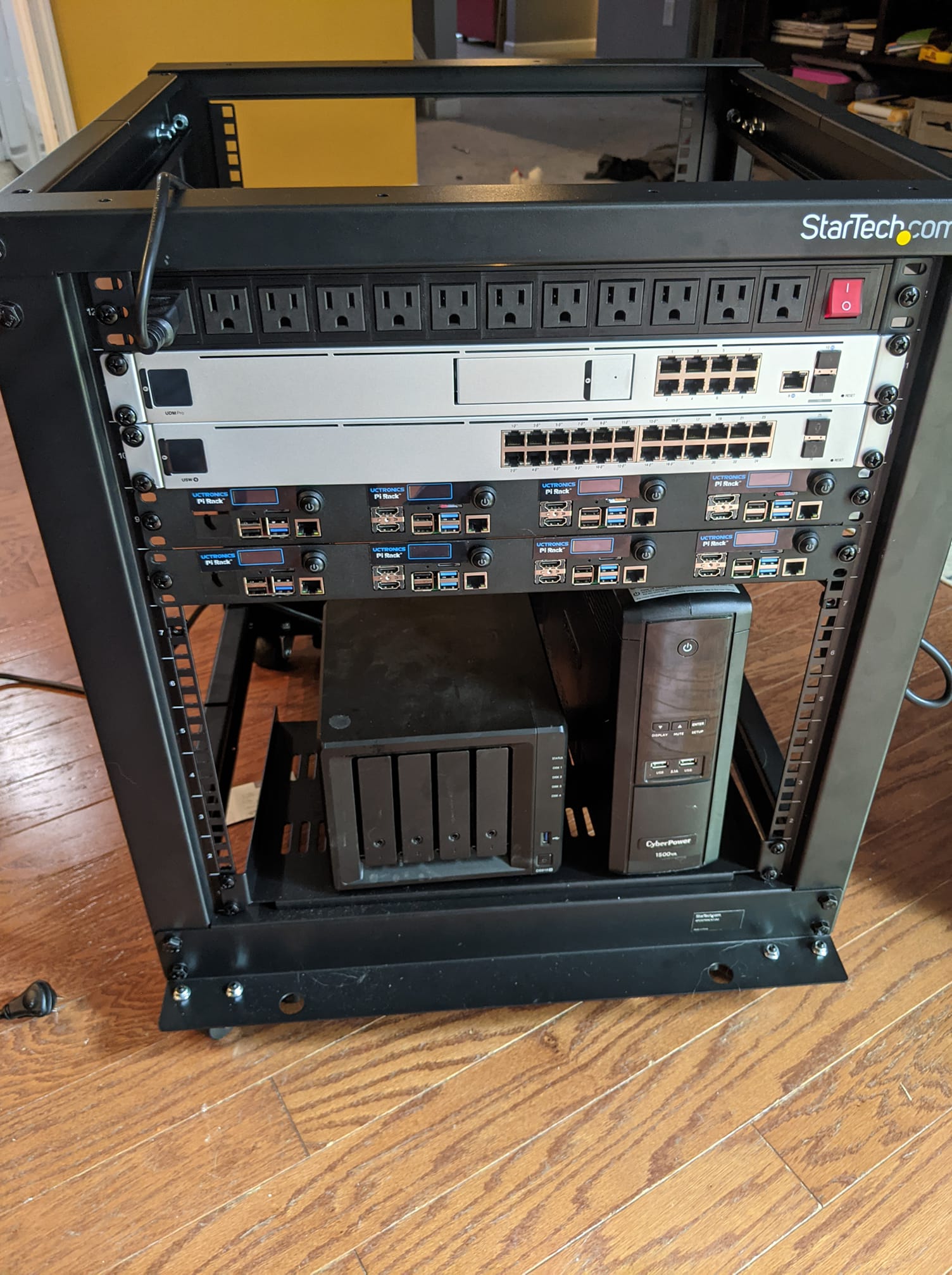
- Server network: My main server stuff is here. A nomad cluster across an i7 server and a bunch of pi’s, also a DS918+. DNS is here because I use Consul with dnsmasq. Some smart stuff lives here like my ecobee.
- IoT Network: the real meat. This is nearly the same as the black hole one except it can talk to the Server Network for C&C (esphome)
The Software
First I played with tasmota and the devices would randomly require me to set them up again.
Have you ever bought a device that turns on, sets up an AP for you to connect to then configure it? Thats a lot like Tasmota.
The problem is that in just a few days I had to set up the same devices multiple times. So I’d go to do something, it wouldnt exist in homeassistant, and Id see a few tasmota-##### AP’s I had to set up again.
I solved this by pulling the source code down, modify the configs (which took a lot of figuring out for the settings), compile it, flash it. Per device.
Then I had to upload the actual config for pins/buttons/etc. I hated this. Every second of it.
After playing around with way too many things, I finally landed on esphome.
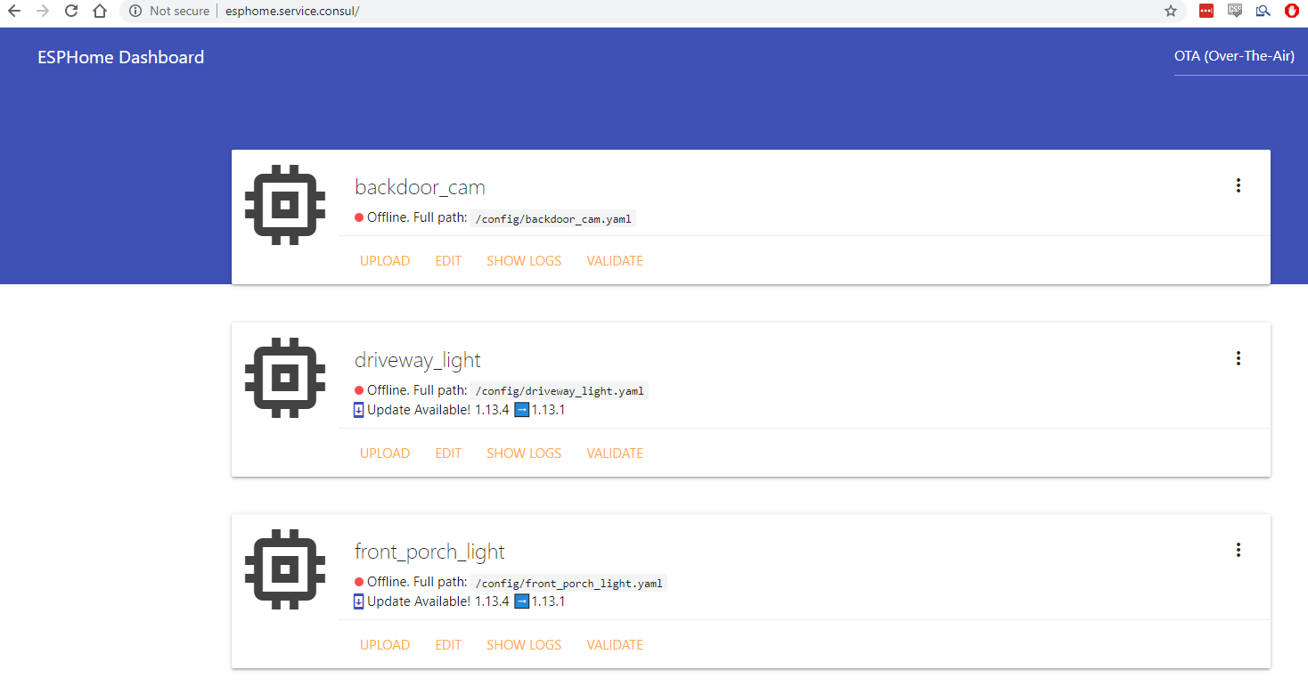
Esphome is amazing. It has over-the-air updates, it automatically compiles based on some yaml and uploads it! If it cant upload it (like the initial flash) I would simply set up the yaml, compile it, SCP it locally and flash it with https://github.com/espressif/esptool. If this worked, it would now support OTA updates.
Because its a bunch of yaml I can source control it too!
It uses passwords for both API integrations (home-assistant) and for OTA updates (same or different password) which makes me feel good.
Also: the server runs as a container, so its running on my Server network on nomad. I can simply go to http://esphome.service.consul and click “Upload” to update my IoT.
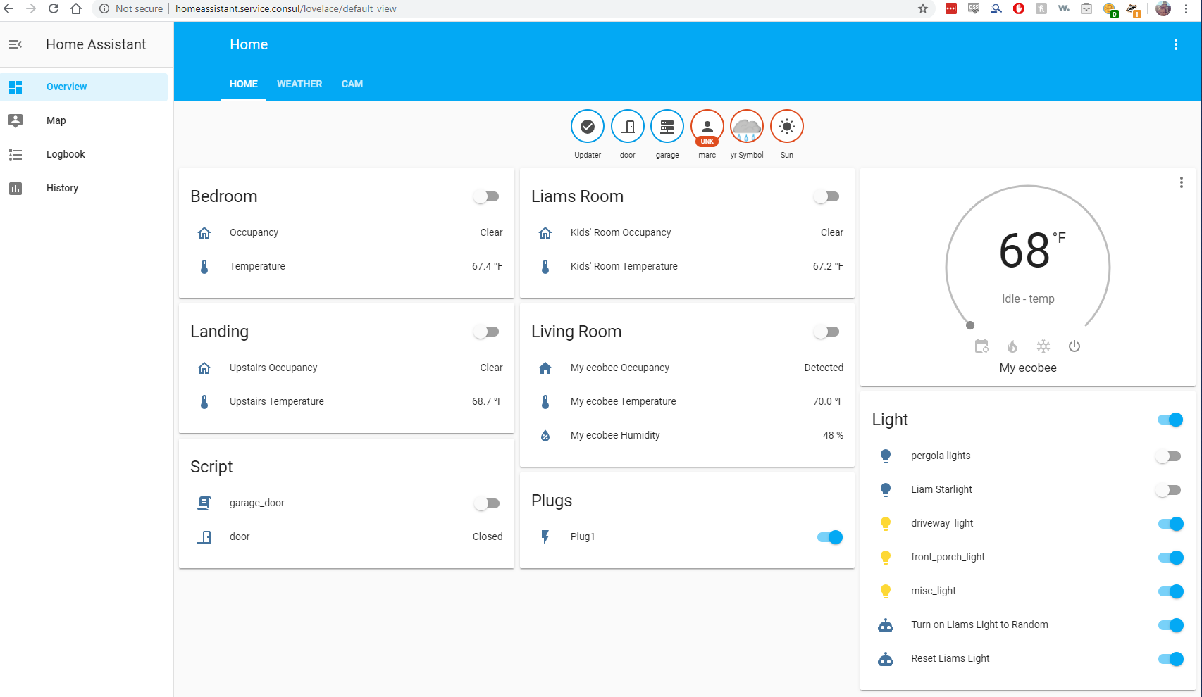
As for the controlling the devices I chose home-assistant. It has great support for ESPHome.
The Devices
This is what you’re really here for. Everything is ESP based for esphome.
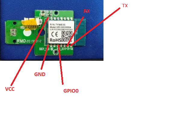
I flashed almost all of these with an ftdi serial adapter and esptool.py similar to
1 2 3 4 5 | |
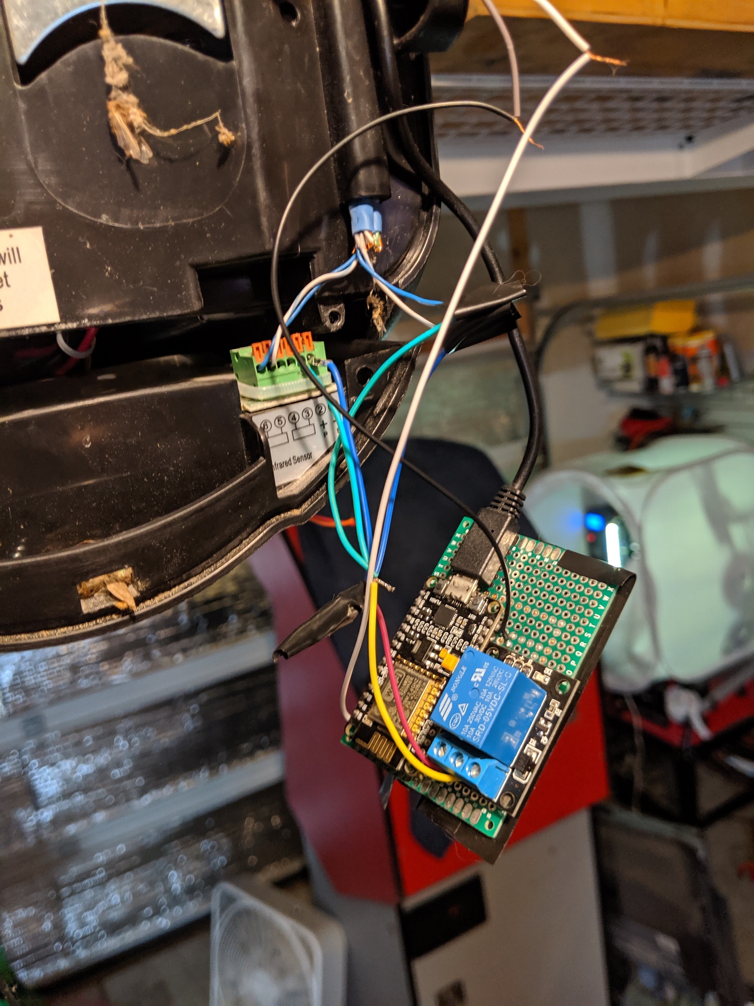
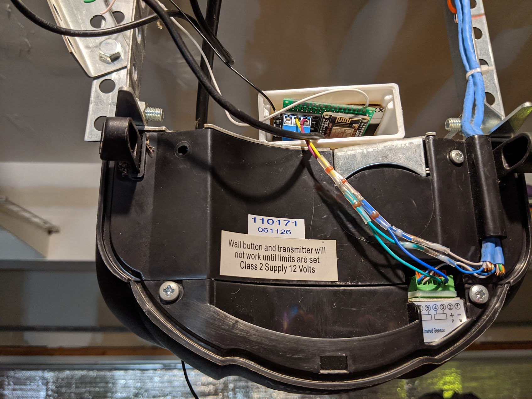
Garage Door Opener
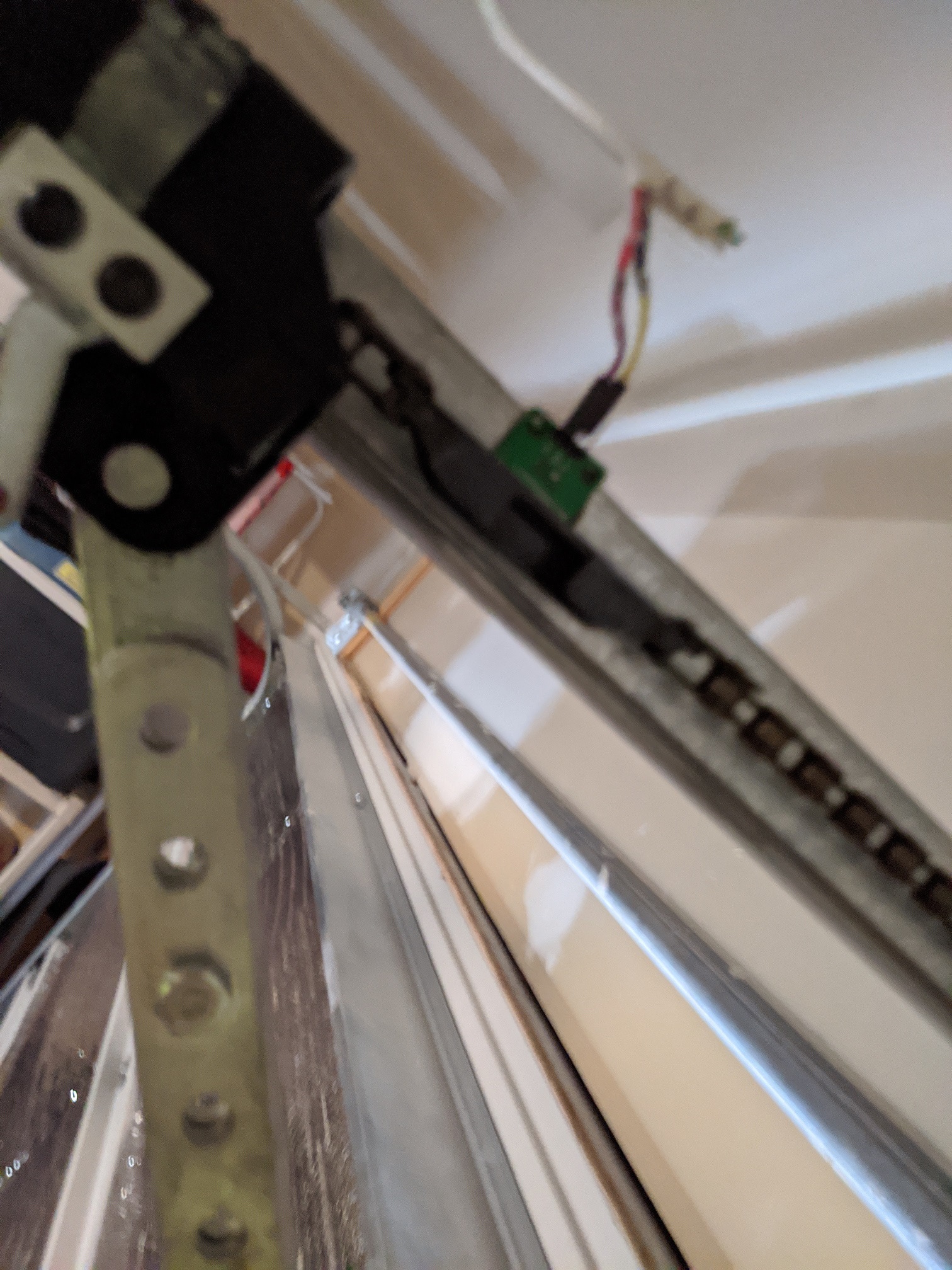
This one took some learning to get right. Its a nodemcu ESP8266 hooked up to a 12v relay shimmed to the garage door trigger. Triggering GPIO16 triggers the relay. Attached to GPIO5 is a reed switch on the garage door track that is open or closed. The reed switch is a magnetic based switch. When a magnet is near it, it breaks the switch (open) meaning the garage door is closed. I wired it this way so that the only way the door can be considered “closed” is that the magnet has broken the sensor. No power, messed up sensor, manually opened (without using the garage door chain) etc would all be considered an open door. I chose this because I’d rather be safe than sorry and the door being closed is not an assumption but a fact.
1 2 3 4 5 6 7 8 9 10 11 12 13 14 15 16 17 18 19 20 21 22 23 24 25 26 27 28 29 30 | |
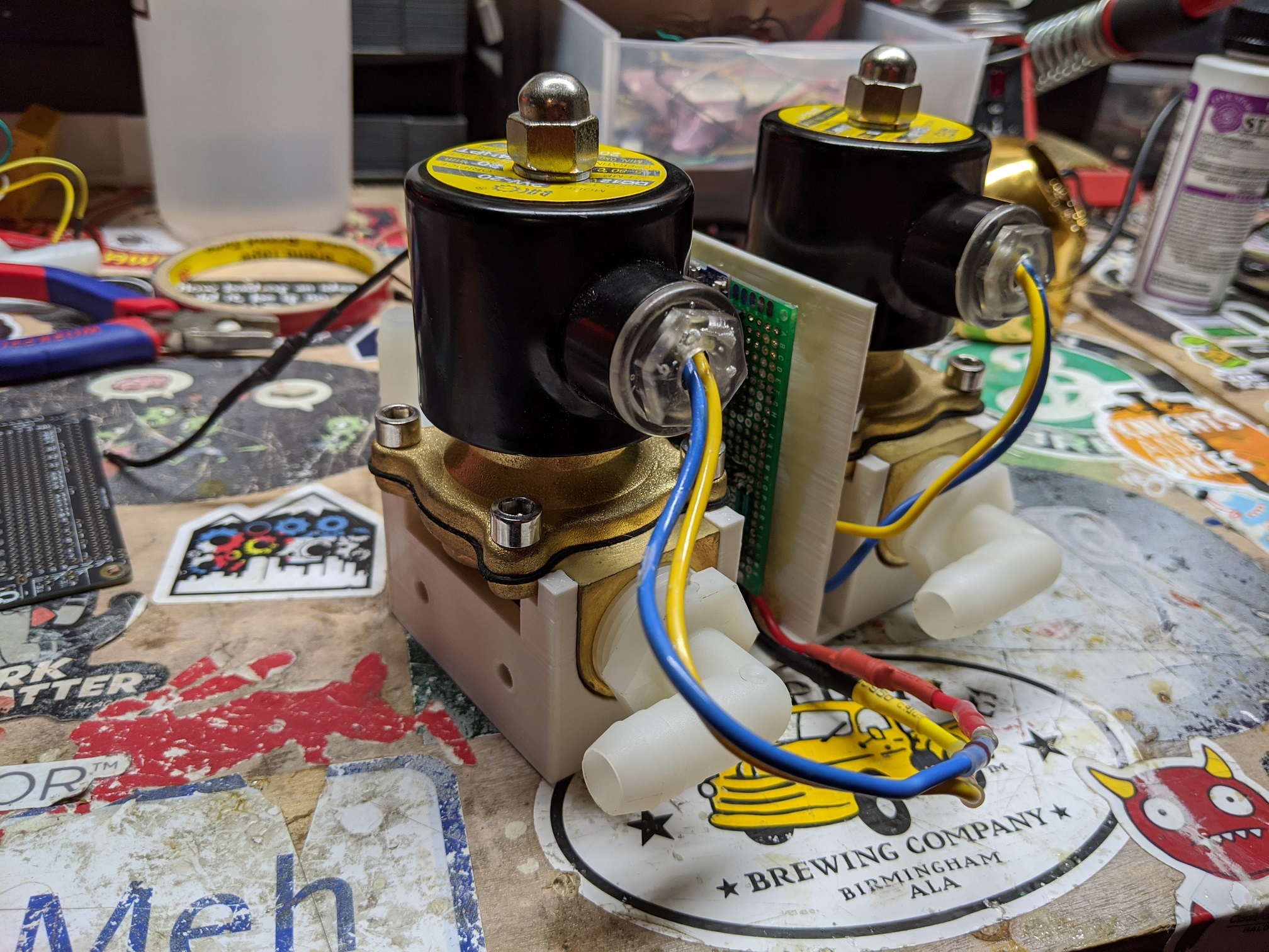
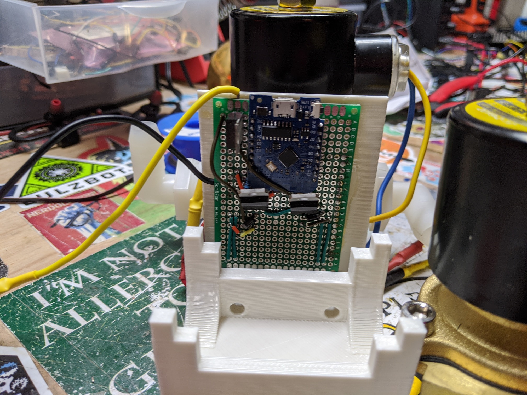
Sprinklers
This one is in progress. It works but I haven’t finished the housing (needs to be gasket based and ABS).
This is based on a wemos d1 mini and is essentially 2 12v solenoid valves on GPIO16 and GPIO14. the 12V is controlled based on circuitry through diodes and TIP120 fed from a 12V source (dropped to 5v via a LM7805 to the d1 mini).

1 2 3 4 5 6 7 8 9 10 11 12 13 14 15 16 17 18 19 20 21 22 | |
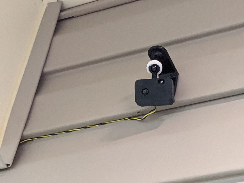
Camera
This one is still a bit in progress. My end goal is to take snapshots on an interval and push them to s3 so that I can play around with machine learning, but right now it lets me view it in hass (no recording as of now).
I chose the esp32-cam because it’s very cheap. That’s all, and it supports esphome. The housing I 3d printed from here
Note: This was a bit annoying to set up the first time. You can’t “just flash it”, you need to set up spiffs correctly. Which looked like this:
1 2 3 4 5 | |
1 2 3 4 5 6 7 8 9 10 11 12 13 14 15 16 17 18 19 20 21 22 23 24 25 26 27 28 29 | |
LED Strips
In the kids room I have some star lights, and on our Pergola I have some waterproof LED lights all controlled with:
This magic home smart controller . I chose this because its ESP8266 based and flashable!
Wiring that up to the FTDI I flashed this yaml:
1 2 3 4 5 6 7 8 9 10 11 12 13 14 15 16 17 18 19 20 21 22 23 24 25 26 27 28 29 30 31 32 33 34 35 36 37 38 39 40 41 42 43 44 | |
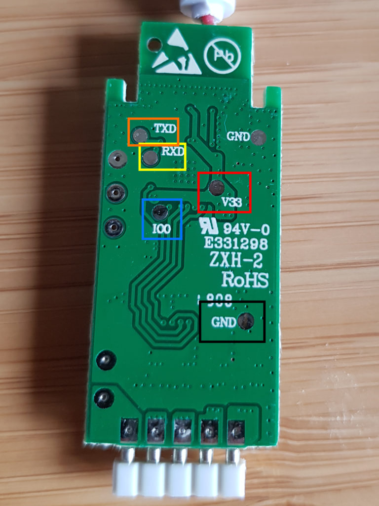
Light Bulbs
For the bulbs I chose globe brand because theyre also ESP8266 based.
For 2 of 3 of these I had success with tuya-convert which was pleasant. Basically I built my .bin from the yaml below, replaced tasmota.bin in that dir with it because I’m sneaky, ran tuya-convert, flipped the light off/on 3 times and it flashed.
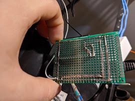
For 2 of them (1 I broke), I had to get down and dirty. I basically tore it apart and followed this guide. Temporarily soldering and removing all the heat safe gunk is not fun. But 1 flashed. 1….caught fire….

1 2 3 4 5 6 7 8 9 10 11 12 13 14 15 16 17 18 19 20 21 22 23 24 25 26 27 28 29 30 31 32 33 34 35 36 37 38 39 40 41 42 43 44 45 46 47 48 49 50 | |
Smart Plugs
These come in handy for seasonal stuff like xmas lights, etc. But especially for my 3d printer as an emergency safe-measure (forget to turn off etc)
I chose the Sonoff S31.

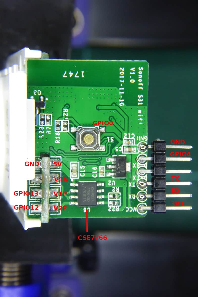
Easy to take apart, a bit annoying to flash (involves temporarily soldering), but work amazingly.
The yaml makes sure that its on by default and that the power button is a hard toggle for the power for manual control. Blue light indicates wifi, red indicates on/off for the relay.
1 2 3 4 5 6 7 8 9 10 11 12 13 14 15 16 17 18 19 20 21 22 23 24 25 26 27 28 29 30 31 32 33 34 35 36 37 38 39 40 41 42 43 44 45 46 47 48 49 50 51 52 53 54 55 56 57 58 59 60 61 62 63 64 65 66 67 68 69 70 71 72 73 74 75 76 77 78 79 80 81 82 83 84 85 86 87 88 89 90 | |
Smart Switch
I kept blowing my outdoor smart bulb, I’m guessing the voltage or current is too volatile?
I chose the TreatLife single pole.
This yaml lets the LED indicator (GPIO4) toggle with the virtual button (GPIO13) and the physical button (GPIO12)
1 2 3 4 5 6 7 8 9 10 11 12 13 14 15 16 17 18 19 20 21 22 23 24 25 26 27 28 29 30 31 32 33 34 35 36 37 38 39 40 41 | |