After two years of failing to deliver a promised feature I decided to reverse engineer and make my own plaato keg firmware
I backed this project because plaato makes really good quality stuff. The idea of having a weight based keg estimator for my barcaderator was key.
They promised multiple times they’d allow people to capture the data themselves. They have yet to deliver.
1 2 3 4 5 6 7 8 9 | |
1 2 3 4 5 6 7 8 9 10 11 12 | |
So I decided: why not do it myself?
In january 2020 I did a PyTN talk about how to sniff the data. While cool, it didn’t really bear much fruit. The amount of effort to make this be my end game was a bit much and I’d be reliant on always intercepting it. I did however know that its got an ESP32-D0W0 (wroom) as the brains and it didnt look that complicated.
So I took it down again and flashed a basic esphome build to it (the code is here.)
This was easier than it looks, you just need a steady hand. Once you flash it the first time you can do pure OTA updates.
I wont go into absolute detail but you can just look at the pinout for the ESP32 and solder leads to the pins directly. RX, TX, Gnd, Vcc, and GPIO (grounded) directly to an FTDI programmer.
First I made a backup of the original firmware:
1 2 | |
Then I flashed the new one built from ESPhome:
1 2 3 | |
Now it shows up in ESPHome as expected!
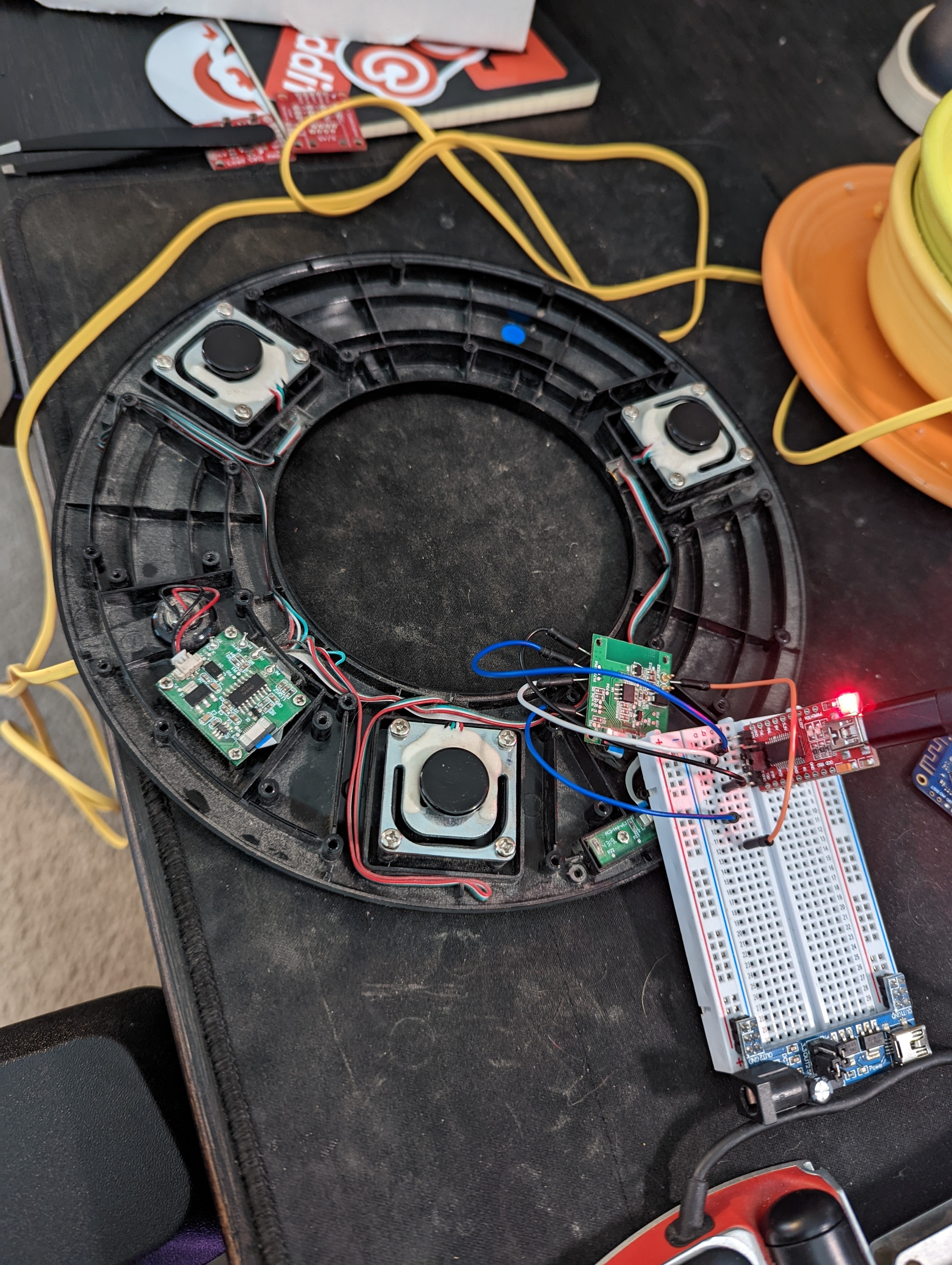
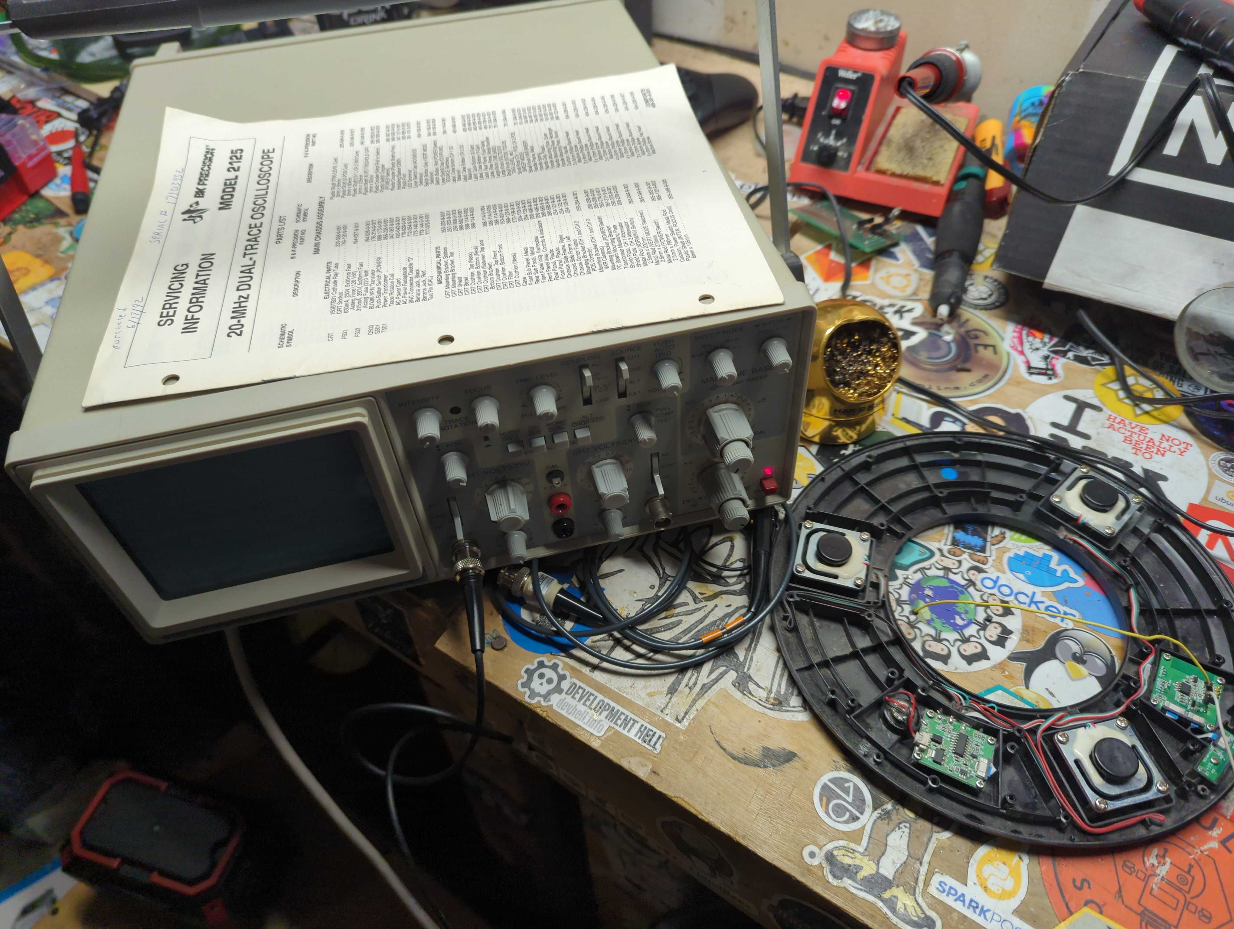
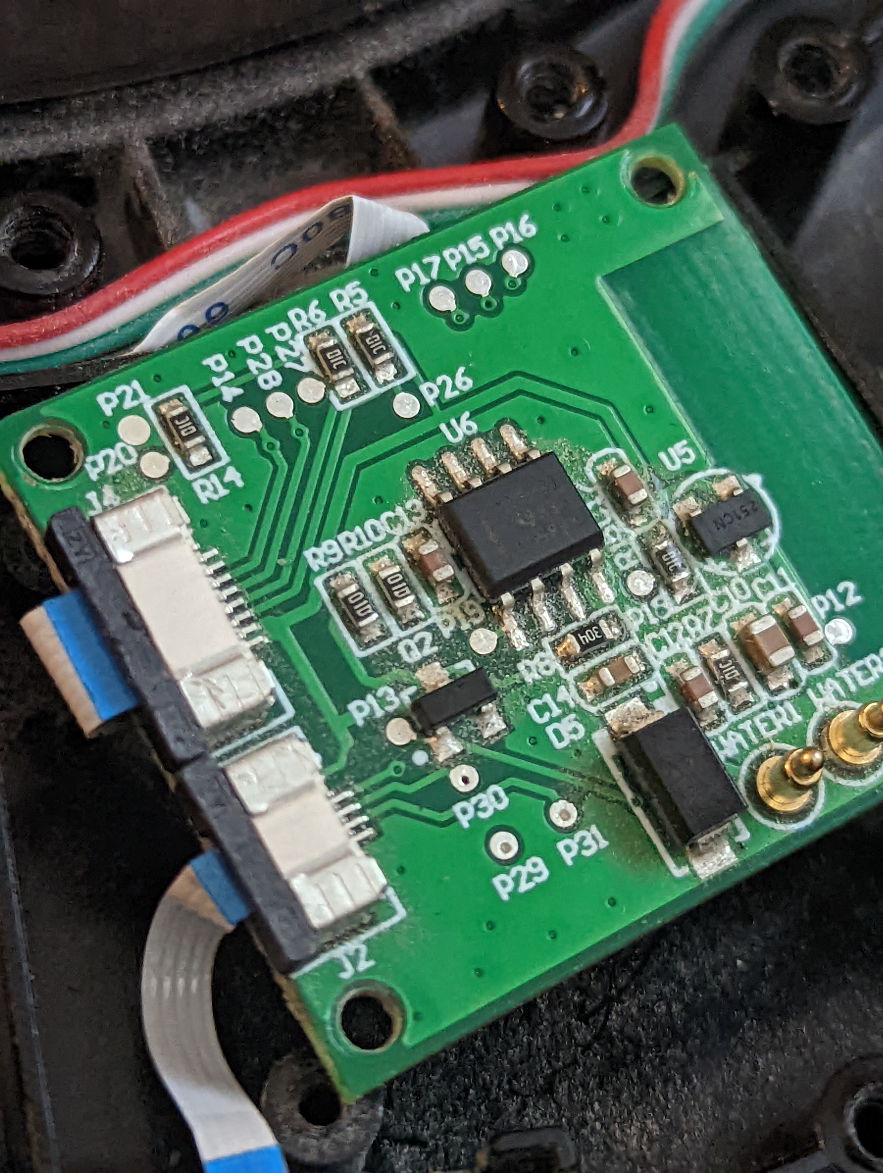
I then used a (very old) osciloscope to try to map out the load cells (load cell combinator is pretty boring (yayyy) and just drags the voltage, ground, data, etc over a ribbon cable to the main PCB. This main PCB uses a P## notation which are not 1:1 with the ESP32 (booooo)
I was able to discover that the clock for this is P14. I then used a multimeter to correlate P14 to GPIO16 (by dragging the other load across all the ESP32 pins until a beep gave it away). I did this to discover the data pin from the load cell combinator is P28. My handy dandy Multimeter let me correlate P28 to GPIO 17 on the ESP32.
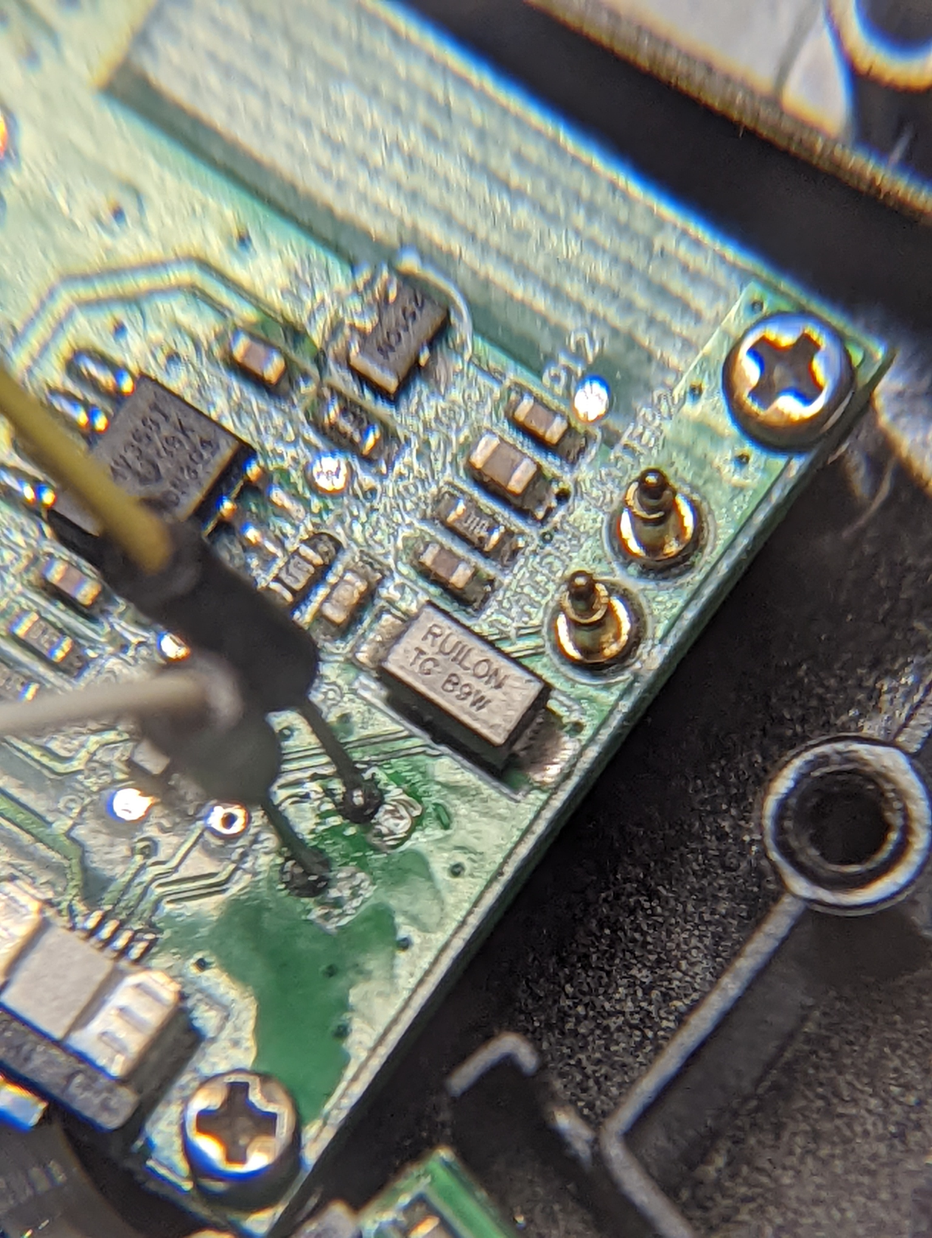
I was able to figure out the LEDs without an oscilloscope by just using a multimeter. The main PCB just uses GPIO to turn those pins high or low to run the 3 LEDs, which is boring (yay).
The rest was trial and error.
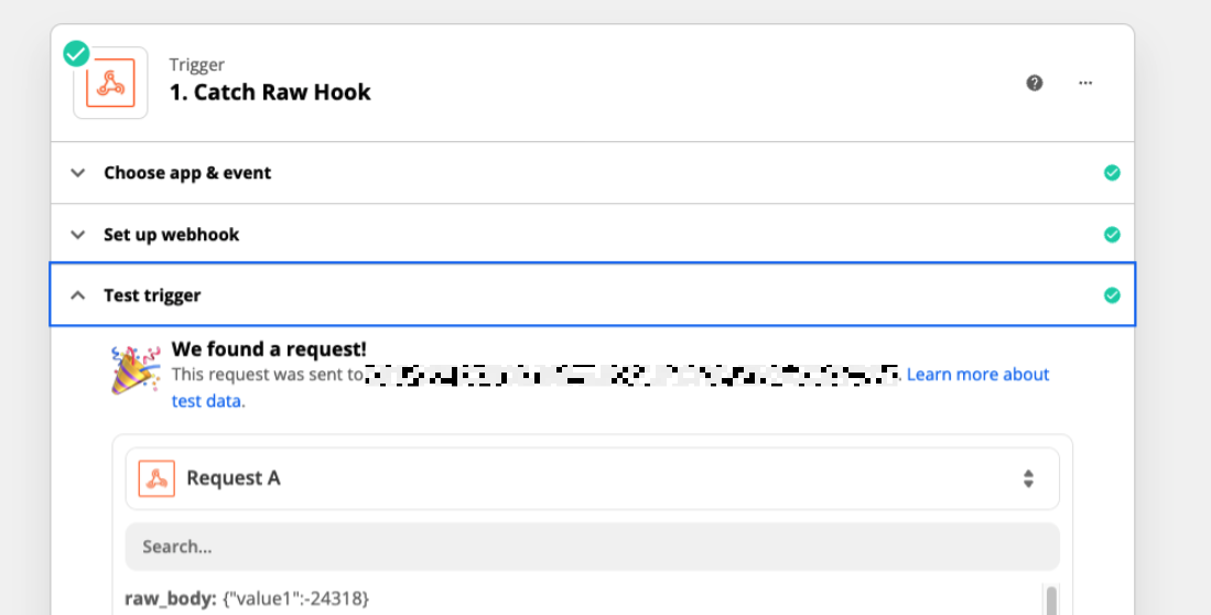
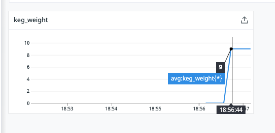
Next I used zapier webhooks to receive the HTTP Post from esphome to send it to Zapier, which then sends it to datadog.
Check out the repo for my up to date esphome yaml